SMA Coax Transitions to Microstrip Modeling with Advanced Design System (ADS) with Experimental Verification
Sasan Ardalan, Extra Class Amateur , AJ7BF
November 28, 2013
(c) 2013 Sasan Ardalan
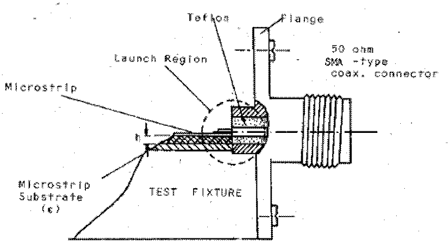
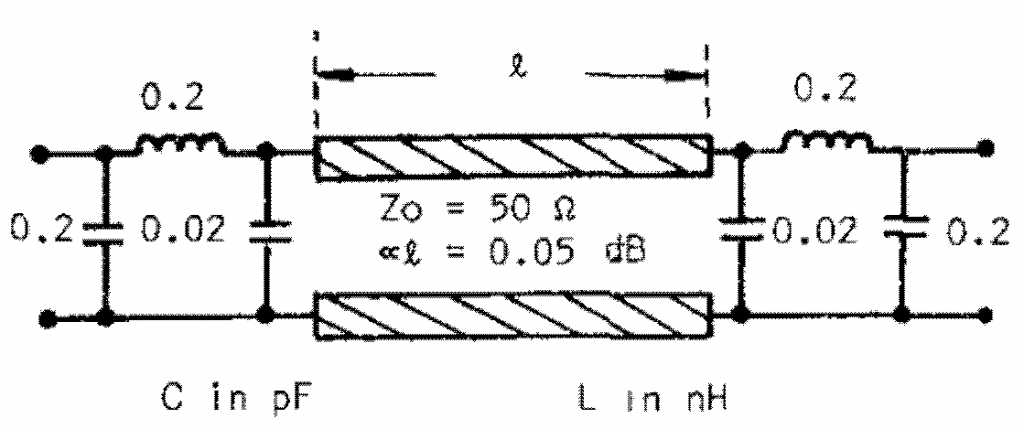
This work is research into the use of SMA connectors in Microwave Circuits. In [Majewski,1981], the Coax to Microstrip Transition shown in Figure 1 was analyzed. They developed a circuit model shown in Figure 2.
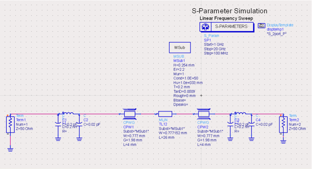
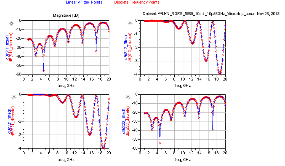
The author developed an ADS [Keysight] model of the circuit in Figure 3. The results are shown Figure 4.
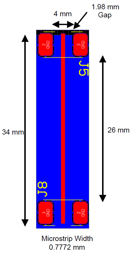
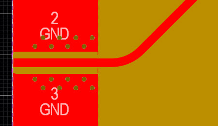
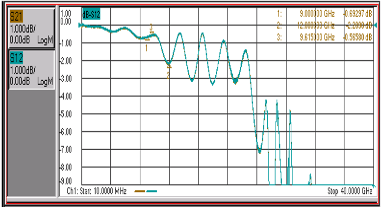
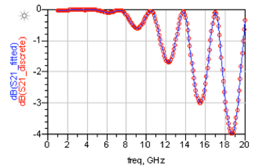
The results clearly show that the SMA connector will fail beyond 6 GHz. This is highlighted in [Majewski,1981]. As will be shown, SMA connectors can be designed that operate up to 125GHz [Southwest Microwave]. Using a conventional SMA connector and using the test structure shown in Figure 5 (10 mil Rogers 5880 50 Ohm Microstrip), we tested the SMA connector. See Figure 6 for good practice in SMA launch using ground vias. The measurement results are shown in Figure 7. The results are a close match to the ADS model shown in Figure 8.
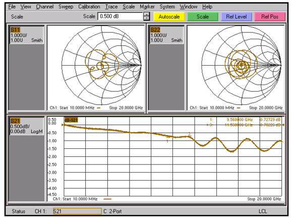
We also tested the same circuit in Figure 5 with Southwest Microwave End Launch SMA Connector [Southwest Microwave]. The results are shown in Figure 9. Clearly a superior performance. Figure 10 shows an example of using the Southwest Microwave connector.

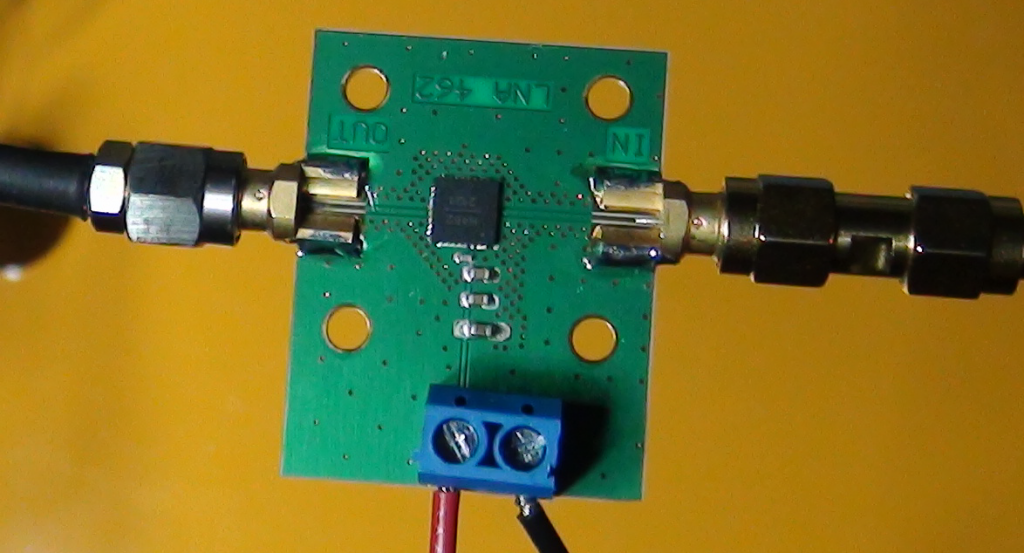
For production we tested the Cinch Connectivity Solutions SMA End Launch Connector. See [Cinch]. A coupon that we developed to test an LNA is shown in Figure 12. The measurement with a Network Analyzer with a frequency span of 40 GHz is shown in Figure 13.
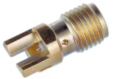
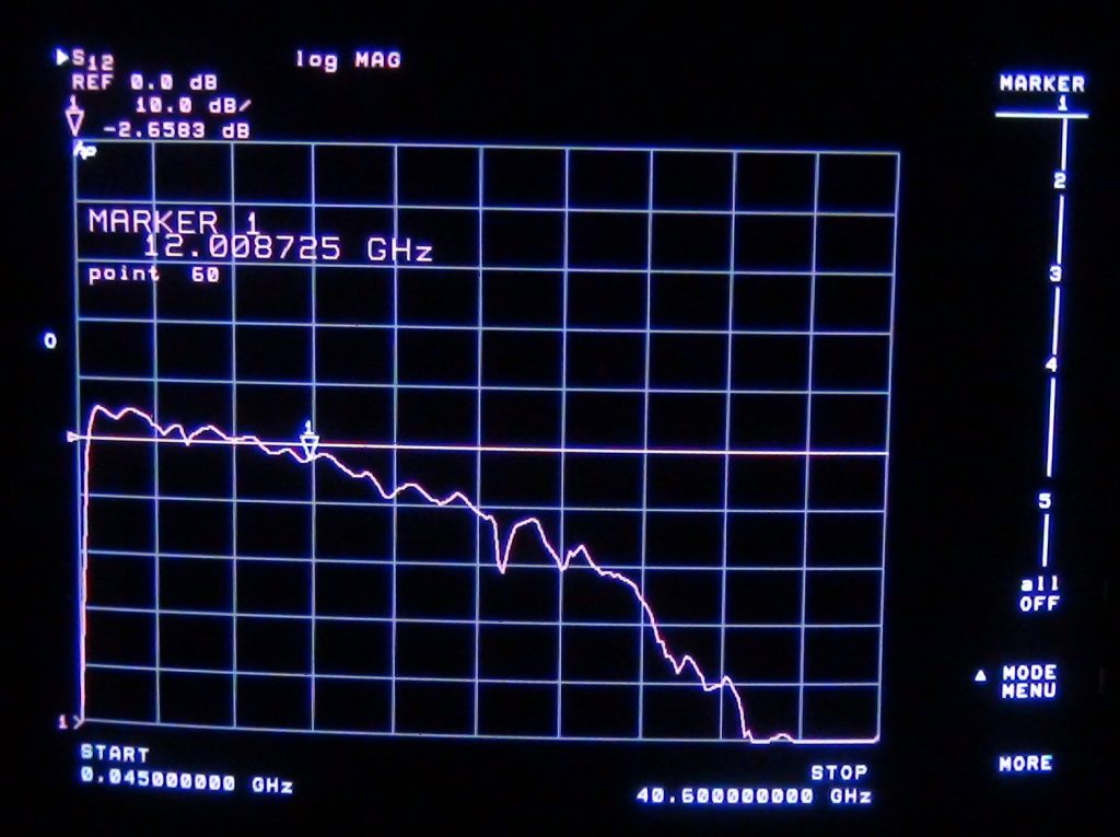
The Cinch SMA connector has excellent performance.
In conclusion, the SMA to Microstrip Transition can be modeled and the model matches measurement. Also, with proper design SMA connectors can perform well at XBand frequencies. See references [Southwest Microwave] and [Cinch].
References
1-Merian L. Majewski, Robert Rose, James R. Scott, “Modeling and Characterization of Microstrip-to-Coaxial Transitions,” IEEE Transactions on Microwave Theory and Techniques, VOL. MTT-29, No. 8, August 1981
2- Keysight, “Advanced Design System (ADS)”,https://us/en/products/software/pathwave-design-software/pathwave-advanced-design-system.html
3- Southwest Microwave, End Launch Connectors, https://mpd.southwestmicrowave.com/product-category/end-launch-connectors/
4-Cinch Connectivity Solutions, “High Frequency SMA End Launch Connectors Part 142-0771-831”,https://www.digikey.com/en/products/detail/cinch-connectivity-solutions-johnson/142-0771-831/726115
